- Original research
- Open access
- Published:
Short-term interaction between electric vehicles and microgrid in decentralized vehicle-to-grid control methods
Protection and Control of Modern Power Systems volume 4, Article number: 5 (2019)
Abstract
In this paper, a particular standard MicroGrid (MG) is accurately simulated in the presence of the Electric Vehicles (EVs) participating in decentralized primary frequency control service. It examines effect of number of the participating EVs on the short-term dynamic behaviour. The simulation results confirm that frequency deviation will not definitely become zero even though an unlimited number of the EVs participate. The output power of each EV is determined according to the frequency deviation. On the other hand, the output power of each EV affects the value of the frequency deviation, especially in small-scale MGs and MGs with predominant inductance behaviour. Eventually, an equilibrium point is reached after a new EV is added that depends on the characteristics of the MG and the functions executed in the MG central controller during such a service. Additionally, effect of Reflex method, an advanced charging technique for EVs, on the frequency deviation is examined.
1 Introduction
Electric Vehicles (EVs) are spreading quickly around the world due to good fuel economy and low pollution emissions [1]. Bidirectional active and reactive power transfer between EVs and MicroGrids (MGs) provides a chance to use them as distributed energy storage units [2–4]. This technology is called Vehicle-to-Grid (V2G) [5] which can provide many services such as reactive power compensation, voltage regulation, harmonic filtering, and primary frequency control [6–11]. This paper focuses on the last service, primary frequency control.
Making appropriate Charging Stations (CSs) and Battery Chargers (BCs) for EVs is one of the essential requirements to successfully implement V2G idea. To participate in primary frequency control service, they must have local control systems to regulate output active and reactive power at desired values. In [12–14], such local control systems have been proposed. Additionally, there is a considerable amount of literature on BCs and CSs with various control systems and control objectives [15–17].
Providing high-quality fast charging services for CSs and BCs persuade people to buy EVs and also participate in V2G technology. Reflex method has considerable distinct advantages compared to other bulk charging methods such as Pulse and CC [14, 18]. In [14], it is concluded that uninterrupted drastic changes in the battery current during the cycles of Reflex method alternately change the output active power of the AC-side terminal of the BC and the CS, negatively affect the AC-side terminal current and therefore, worsen the power quality. This research study examines such an effect on a MG whose frequency is not imposed by the upstream power system, unlike what has been discussed in [14].
Defining a control framework is an essential requirement to successfully realize V2G concept. There are many different studies conducted on V2G control [6, 7, 19–23], but our control framework is completely based on what has been proposed in [8], a particular decentralized V2G control framework for primary frequency regulation considering charging demands, because it considers the most complete form. Previous studies on V2G control have been limited to the simple models of EVs and Distributed Energy Resources (DERs) [8, 19–24], while an attempt to model them based on their power converters and control systems has been done in this paper in the light of recent relevant studies [14, 25–27]. It enables future researchers to simulate V2G in short-term periods accurately.
The present paper aims to examine effect of number of the EVs participating in decentralized V2G technology, primary frequency control service, on short-term dynamic behaviour of the MG when the framework proposed in [8] is utilized. The short-term dynamic behaviour of a particular standard IEEE MG in the presence of the EVs participating in it is accurately simulated. This purpose gives a clear and better view of the decentralized V2G control proposed in [8] a the short intervals. Additionally, it aims to examine effect of Reflex method, an advanced charging technique, on the MG whose frequency is not imposed by the upstream power system, unlike what has been discussed in [14].
This paper is divided into five sections. Section 2.1 concerns models and control systems in the MG. The simulation results are discussed in Section 2.2 and eventually, it finishes with conclusion in Section 3. Section 4 presents the parameters for simulation.
2 Methods
2.1 Models and control systems
The MG shown in Fig. 1, which is one part of North American medium voltage CIGRE-IEEE DER benchmark system adopted from [28, 29], has been augmented by three DERs arbitrarily selected as shown in Fig. 2. Appendix gives all parameters of the MG. The Point of Common Coupling (PCC) in the MG can be disconnected and it is intended to operate in the following two different operating conditions: [27]
-
Emergency mode
Fig. 1 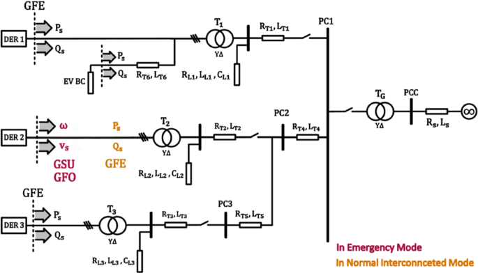
Control structures in the two operation modes in the MG
Fig. 2 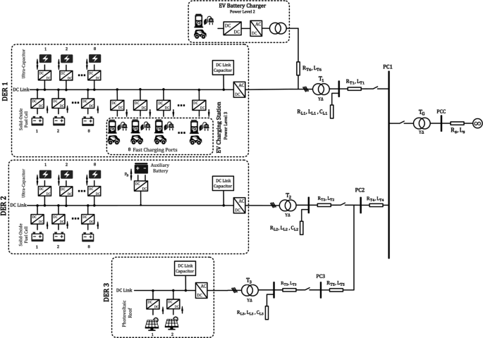
Details of the MG
-
Normal interconnected mode


The MG is centrally controlled and managed by a MG Central Controller (MGCC) installed at the MV substation.
In recent studies conducted on voltage and frequency control of MGs [26, 27, 30, 31], different control schemes based on different concepts to operate power converters in both modes under supervision of MGCC have been presented. Three kinds of control structures may be used to operate a power converter [26, 32, 33]:
-
Grid-Forming (GFO):
It keeps vs and ωs constant and equal to the given reference commands v∗ and ω∗.
-
Grid-Feeding (GFE):
It regulates Ps and Qs at the corresponding reference commands \(P_{s}^{\ast }\) and \(Q_{s}^{\ast }\).
-
Grid-Supporting (GSU):
It regulates vs and ωsclose to their rated values, vref and ωref.
DER 1 and DER 2 are dispatchable and DER 3 is non-dispatchable. DER 1 and DER 3 operate as GFE power converters in both modes, while DER 2 operate as GSU power converter in the emergency mode and GFE in the normal interconnected mode as shown in Fig. 1.
2.1.1 DC-AC stage
Figure 3 show control systems of the power converters shown in Fig. 2, DC-DC and DC-AC stages. The relevant equations and the stability analysis have been examined and studied in detail in [14, 25, 32, 33]. Thus, it is not necessary to examine again. In Fig. 3, S0 is set in the up situation when it works in GSU structure and is set in the down situation when it works in GFE structure. In the up situation, there are inner current control loops and outer voltage control loops while in the down situation, there are only inner current control loops with DC link voltage control loop in order to implement their own control objectives [25, 26, 32, 33]. The common part in both situations is two current control loops in dq frame which receive references of the three-phase currents in dq frame (idref and iqref) and finally transform them to the switching functions of IGBT legs based on PWM strategy. All the variables are first transformed from abc frame to dq frame. After passing through some transfer functions in dq frame, they are then transformed from dq frame to abc frame. Phase of the three-phase terminal voltages (vsa, vsb, and vsc) is detected by the phase-locked loop (PLL) in the down situation or is made by an integrator in the up situation [25, 33].

Power converters in the MG and their control systems
In the down situation, idref and iqref are calculated so that Ps and Qs follow Ptot and \(Q_{s}^{\ast }\), respectively. Ptot becomes equal to Pext (iext×vDC) when vDC reaches its steady state value (\(v_{DC}^{\ast }\)). On the othe hand, the control system for vDC aims to regulate vDC at \({v_{DC}^{\ast }}\) with considering Pext as a disturbance. In conclusion, it keeps Ps, Qs, and vDC equal to \(P_{ext}^{}\), \(Q_{s}^{\ast }\), and \(v_{DC}^{\ast }\), respectively. This means that to have \(P_{s}^{\ast }\) at the output, Pext which is imposed by the DC-DC stages must be regulated at \(P_{s}^{\ast }\). The relevant equations and the stability analysis can be found in detail in [14, 25, 33].
In the up situation, idref and iqref are adjusted by the voltage control loops so that vd and vq become equal to vdref and vqref which are calculated by the droop control block with the output virtual impedance block. This means that the control system keeps the terminal three-phase voltages sinusoidal with defined amplitude, phase, and frequency which are defined by the droop control block and the output virtual impedance block. The droop control algorithms are implemented in GSU power converters without using communication channels in order to keep voltage and frequency under control. Performance of the conventional droop control is highly dependent on R/X of the line [30]. Due to this feature, this method cannot be directly applied in all kinds of networks [26, 31], unless sophisticated impedance estimation algorithms are implemented. An intuitive solution to solve such a drawback, resulting from the strong dependence of the conventional droop controller performance on the line impedance, has been successfully introduced in [26] where an adjustable virtual output impedance has been used. It is worth to remark that the value of the virtual output impedance should be larger than the value of the actual line impedance; Otherwise, it will not have predominant effect in power flow equations. The virtual output impedance modifies the output voltage reference of the power converter so that vsa, vsb, and vsc are obtained by subtracting the virtual voltage drop across the virtual output impedance (Zvir or Rvir with Lvir) from the output voltage reference originally provided by the signal generator as shown in Fig. 3 [26]. To have vsa, vsb, and vsc with the desired amplitude vref, the initial phase ϕ0, and the frequency ωref, the signal generator receives vref and ωref from droop control block, makes the symmetrical three-phase signals and then, subtracts the three-phase abc virtual voltage drops caused by Lvir and Rvir. Finally, the result is the three-phase terminal voltage references in abc frame which are transformed to dq frame (vdref and vqref). The droop control block in predominant inductance behaviour can be found in [26]. The relevant equations and the stability analysis are detailed in [25, 33].
2.1.2 DC-DC stage
The DC-DC power converters have two control objectives (see Fig. 3). First, they are responsible for extracting or injecting power from or to the DC voltage sources such as Solid-Oxide Fuel Cells (SOFCs), battery packs, UltraCapacitors (UCs), and photovoltaic roofs. The letter x can be replaced with FC, PV, Bat, and UC. These elements impose Pext in the DC-AC power converters. Thus, the control systems of the DC-DC power converters aim to regulate:
-
PBat at \(P_{Bat}^{\ast }\)
-
\(P_{FC}^{}\) at \(P_{FC}^{\ast }\)
-
PUC at \(P_{FC}-P_{FC}^{\ast }\). The SOFC stacks cannot respond quickly to \(P_{FC}^{\ast }\). Thus, the UCs aid the SOFC stacks to set Pext at \(P_{FC}^{\ast }\). They compensate the power difference in order to keep Pext constant and equal to \(P_{FC}^{\ast }\).
Second, they are responsible for controlling the corresponding DC link voltage vDC at \(v_{DC}^{\ast }\). Therefore, DC link voltage is controlled by them in GSU power converters while it is controlled by the MG in GFE power converters [25, 32, 33].
2.2 Control functions in the MGCC
Figures 4 and 5 show the control functions in the first hierarchical control level that are executed in the MGCC. Figure 4 includes three parts as follows:
-
The first part pertains to DER 1. It introduces \(P_{FC}^{\ast }\), \({P_{Cap}^{\ast }}\), and \(Q_{s}^{\ast }\) for DER 1. Since there are eight SOFC stacks and eight UCs, the output power reference C1 is divided by 8 and then, is given to \(P_{FC}^{\ast }\). The UCs generate or absorb the active power difference until \(P_{FC}^{}\) becomes equal to \(P_{FC}^{\ast }\). Extracted or absorbed power by the UCs changes their voltage level. Therefore, an internal control system for maintaining the voltage of the UCs between allowable limits is needed. S2 and S3 are set in the down situations as soon as secondary frequency control stage is activated. The frequency and voltage errors calculated from the local control system of DER 2 (Δf2 and ΔE2) are used to determine \(P_{s}^{\ast }\) and \(Q_{s}^{\ast }\) of DER 1. DER 1 adjusts \(P_{s}^{\ast }\) and \(Q_{s}^{\ast }\) to make the errors equal to zero.
Fig. 4 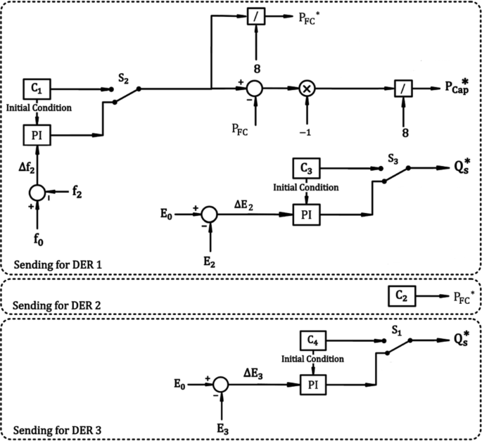
Control functions in the MGCC
Fig. 5 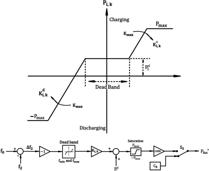
Pi,k in terms of Δfk in charging with frequency regulation method
-
The second part pertains to DER 2. The output power reference C2 for each stack is given to \(P_{FC}^{\ast }\). It is worth mentioning that the AC-side output active power of all AC-DC power converters Ps is equal to the net value of the injected power to their corresponding DC link in steady state condition (when vDC becomes equal to \(v_{DC}^{\ast }\).) if conduction and switching losses are neglected [25].
-
The third part pertains to DER 3. In Fig. 4, the line-to-line voltage of PC3 is measured to calculate \(Q_{s}^{\ast }\) for sending to DER3. In fact, the output reactive power of DER 3 can regulate the voltage of the loads connected to PC3. S1 is set in the up situation if the voltage drops significantly. Otherwise, it can indirectly help DER 2 for voltage and frequency regulation.


Frequency regulation and EV owners’ demands are two important concerns that need to be handled [8]. The principal challenge is to maintain a balance between frequency regulation from the power system operator and EV owners’ demands. The coordination between them is of great importance. Therefore, some methods have been developed to deal with such a question in [8, 19–21]. Charging with frequency regulation method [8] has been considered in this research study.
This method adjusts Pi,k, the reference command of the input active power of ith EV at the time k, according to Fig. 5 [8]. \(K_{i,k}^{c}\) and \(K_{i,k}^{d}\) are set according to Fig. 5 and the relevant formulas in [8]. To implement various charging-discharging scenarios, this method is perfectly suitable because the dead band and all the indicated parameters are fully adjustable. Frequency of the MG is monitored by a frequency detection block in real time [8] and then, V2G control block in the MGCC makes decisions based on the real-time frequency and the battery SOCs sent from the frequency detection block and the battery management systems embedded in EVs, respectively. Then, the real-time reference command is produced and sent by V2G control block to the local control system of each EV BC. When the frequency of the MG goes downwards, the EVs reduce consumption or may return energy to the MG. On the other hand, when the frequency of the MG goes upwards, the EVs increase consumption and are charged with higher power level. The function shown in Fig. 5 is executed at the higher hierarchical control level for each EV BC participating in V2G technology. S5 is in the down situation when the EV is charging with a constant power (C6) without considering the frequency deviation (dumb charging).
3 Results
MATLAB software has been used to analyze and simulate the dynamic behavior of the MG with a time step of 1 μs.
3.1 Primary and secondary frequency control
Figure 6a to d show the simulation results for the MG in which only one EV is connected to the primary side of the first transformer and one EV is connected to the CS. Frequency and Voltage must be stable and converged to zero to confirm that DER 2 is able to control frequency and voltage of the MG in emergency mode. Both of them participate in V2G technology according to Fig. 5 based on "charging with frequency regulation" method at t=1s. Before t=1s, they are charging based on "dumb" method, with constant continuous current. The task of secondary frequency control has been done by DER 1 and has been activated at t=1.5s. The MGCC can adjust Ps of DER 1 at \(P_{s}^{\ast }\) quickly to regulate f at f0 and Qs of DER 1 at \(Q_{s}^{\ast }\) to regulate E at E0. This procedure is followed according to Fig. 4. The SOFC stacks in DER 1 cannot respond quickly to \(P_{s}^{\ast }\). Thus, the UCs aid the SOFC stacks to set Ps at \(P_{s}^{\ast }\). They compensate the power difference in order to keep Ps constant and equal to \(P_{s}^{\ast }\). The frequency and voltage errors calculated from the droop control block of DER 2 (Δf2 and ΔE2) are used to determine \(P_{s}^{\ast }\) and \(Q_{s}^{\ast }\) of DER 1 as illustrated in Fig. 4. DER 1 adjusts \(P_{s}^{\ast }\) and \(Q_{s}^{\ast }\) to make the errors equal to zero. After t=1.5s, the SOFC stacks increase generation until their output power become equal to \(P_{s}^{\ast }\) which has been suggested by the control loop in Fig. 4. For this purpose, the input hydrogen flow in each SOFC stack is increased (see Fig. 6a– xH2). As soon as their output power become equal to \(P_{s}^{\ast }\), the input power of the UCs becomes approximately zero and as a result, the voltage of the UCs becomes constant. This is in agreement with the simulation results in Fig. 6a. Figure 6b confirms that DER 2 is able to impose the frequency and the voltage on PC2. Figure 6b – vref and fref show the amplitude of the voltage and frequency which are suggested by the droop control block. Ps and Qs of DER 1 are increased to regulate f at f0 and E at E0. On the other hand, Ps and Qs of DER 2 are decreased because only DER 1 is responsible for power balance in the MG. DC link voltage of each DER has been regulated at 1200 V(\(v_{DC}^{\ast }=1200\) V).

Primary and Secondary Frequency Control. a Important waveforms of DER 1. b Important waveforms of DER 2. c Important waveforms of DER 3. d Important waveforms of the EV BC
3.2 Effect of number of the EVs
Figure 7a to d show the simulation results for the MG in which only one EV is connected to the primary side of the first transformer and some EVs are connected to the CS. All of them participate in V2G technology according to Fig. 5 based on "charging with frequency regulation" method after t=1s. Before t=1s, they are charging based on "dumb" method. The number of the EVs connected to the CS is increased for each 0.5 second after t=1s. V2G technology is activated at t=1s, while secondary frequency control stage is not activated. The MGCC adjusts Pi,k, the reference command of the input active power of ith EV at the time k, according to Fig. 5. \(K_{i,k}^{c}\) and \(K_{i,k}^{d}\) are set according to the equations 5 to 9 proposed in [8]. These parameters are given in Appendix. It is worth mentioning that the frequency of the MG in steady state condition during primary frequency control stage depends on the characteristics of the MG and the functions executed in the MGCC for the EVs participating in V2G technology. It is obvious that this value is not equal to f0 (see Fig. 7b – fref and vref). In other words, the EVs can improve the stability of the MG, but cannot regulate f exactly at f0 because the executed functions (see Fig. 5) are open-loop functions. The simulation results confirm that the EVs can effectively improve primary frequency regulation as expected.

The Effect of number of the participating EVs. a Important waveforms of DER 1. b Important waveforms of DER 2. c Important waveforms of DER 3. d Important waveforms of the EV BC
It is concluded that increase in the number of the EVs participating in V2G technology (in this scenario, for each 0.5 seconds) leads to less frequency deviation as expected, but certainly not zero because the executed functions in the MGCC for them are open-loop functions. The frequency deviation will not definitely become zero even though a lot of EVs participate (see Fig. 7b– fref). It is assumed that all the EVs have the same functions of Pi,k (the function shown in Fig. 5). The output power of each EV BC (Ps) is determined by the corresponding function for each EV shown in Fig. 5 according to the frequency deviation. On the other hand, the output power of each EV BC (Ps) affects the value of the frequency deviation. Eventually, an equilibrium point for the frequency deviation and Ps is reached after a new EV is added (see Fig. 7d – Ps and b – fref). In fact, the equilibrium point when a new EV is added depends on the characteristics of the MG and the functions executed in the MGCC. Furthermore, increase in the number of the EVs results in power sharing between them (in other words, results in reduction in their discharging speed) as expected and also, can cause the EVs to change the operating modes from discharging to charging, even when the frequency is under the nominal frequency (see Fig. 7b – fref). After t=2s, there is no need for the EV (see Fig. 7d – PBat) to be discharged. It reduces its charge speed to help the MG to be more stable with less frequency deviation. In fact, the EVs sometimes are not required to be discharged. The EVs can aid the MG in keeping balance between electricity generation and consumption and can aid it in stability and primary frequency control stage. All the mentioned facts are in agreement with the simulation results shown in Figs. 7b – fref and 6b – fref. The output power of the SOFC stacks in DER 1 and DER2 has been adjusted at 100 kW during the simulation.
3.3 Effect of reflex method on the MG
Reflex method has considerable distinct advantages [14, 18] (and also the references 15 to 23 in [14]). This subsection examines the effect of Reflex charging method on the MG whose frequency is not imposed by the upstream power system, unlike what has been discussed in [14]. Figures 8 and 9 show comparative simulation results for the MG in which only one EV is connected to the primary side of the first transformer and uses Reflex-based bulk charging service. Uninterrupted drastic changes in the battery current during the cycles of Reflex bulk charging method (see Fig. 8 – iBat) alternately change the output active power of the AC-side terminal of the EV BC (see Fig. 8 – Ps), negatively affect the AC-side terminal current is, and therefore, worsen the power quality. This fact has been fully discussed in the simulation results in [14]. Moreover, a new power electronic topology to solve the power quality problem has been proposed in [14]. This subsection examines effect of such a problem on the MG whose frequency is not imposed by the upstream power system (the MG in emergency mode), unlike what has been discussed in [14]. In this regard, it is assumed that the EV BC works in two different scenarios:
-
1.
It works based on Reflex method in the MG in emergency mode. It has the conventional power electronic system with the power quality problem caused by Reflex.
Fig. 8 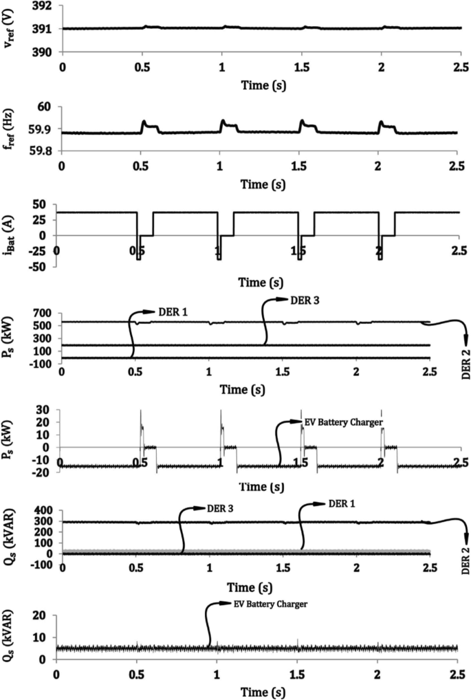
The effect of Reflex method on the MG in scenario 1
Fig. 9 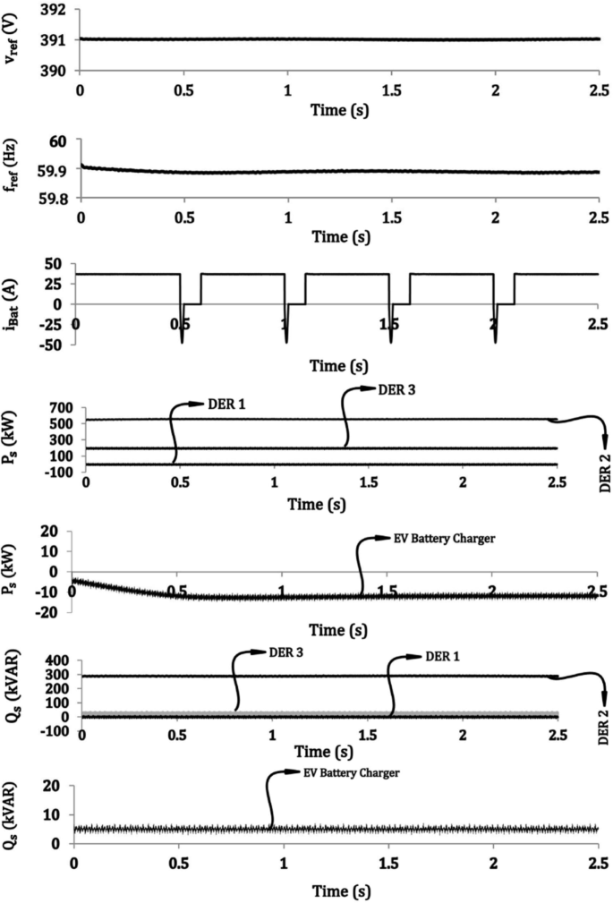
The effect of Reflex method on the MG in scenario 2
-
2.
It works based on Reflex method in the MG in emergency mode, but it has the power electronic system proposed in [14]. This means the power quality problem does not exist.


Figure 8 depict the important signal waveforms when scenario 1 is considered. The frequency (Fig. 8 – fref) encounters variations as a consequence of the changes in the output active power of the AC-side terminal of the EV BC (Fig. 8 – Ps) caused by Reflex. As expected, the changes in the voltage (Fig. 8 – vref) must be relatively smaller because the MG has a predominant inductance behaviour [30] and voltage and active power are almost independent. Figure 9 depict the important signal waveforms when scenario 2 is considered. Because the power electronic system proposed in [14] has been utilized, the output active power of the AC-side terminal of the EV BC (Fig. 9 – Ps) has been regulated at a constant value without any variations. Figure 9 – fref reveals that the power quality problem does not exist. In both scenarios, the output reactive power of the AC-side terminal of the EV BC (Figs. 8 – Qs and 9 – Qs) can be adjusted independently of Ps.
4 Conclusion
The purpose of this paper was to examine the effect of number of the decentralized EVs participating in V2G technology, primary frequency control service, on short-term dynamic behaviour of the MG. It was concluded that the frequency deviation will not definitely become zero even though a lot of EVs or an unlimited number of EVs participate. The output power of each EV is determined according to the frequency deviation. On the other hand, the output power of each EV affects the value of the frequency deviation. This happens especially in small-scale MGs and MGs with predominant inductance behaviour. Eventually, the frequency deviation and the output power become stable and reach new values. An equilibrium point is reached after a new EV is added that depends on the characteristics of the MG and the functions executed in the MGCC for decentralized V2G technology. Additionally, the effect of Reflex method on the MG in the emergency mode was examined and it was revealed that the uninterrupted drastic changes of the battery current of the EVs connected to the CS providing such an advanced charging service cause variations in the frequency of the MG while the EVs are helping the MG in decentralized V2G technology.
5 Appendix
Required Parameters
\(\bigstar \) Transformers [28]
T1: 500 kVAR
Line to line nominal voltage: 12470/480 V
T2: 500 kVAR
Line to line nominal voltage: 12470/480 V
T3: 250 kVAR
Line to line nominal voltage: 12470/480 V
T4: 50 kVAR
Line to line nominal voltage: 480/240 V
TG: 1.25 MVAR
Line to line nominal voltage: 230k/12470 V
Impedances have been referred to the low-voltage side.
[ L1L2L3L4LG]=
[0.0978 0.0978 0.163 0.1711 4.1115] mH
[ R1R2R3R4RG]=[2.304 2.304 3.84 44.5 13] m Ω
\(\bigstar \) Lines and Loads [28]
[ RL1RL2RL3]=[810 420 640] Ω
[ LL1LL2LL3]= [2.86 1.8 3.5] mH
[ CL1CL2CL3]=[1.38 1.83 0.64] μF
[ RT1RT2RT3RT4RT5RT6Rs]=
[0 0 0 0.846 0.517 0 0.439] Ω
[ LT1LT2LT3LT4LT5LT6Ls]=
[0 0 0 5.603 3.427 0 11.635] mH
\(\bigstar \) DER 1
[L]=[1] mH
[ CDC]= [3] mF
[\(v^{\ast }_{DC}\)]=[1200] V
[ Rint]=[30] m Ω
Parameters of Fig. 5 for the EV CS:
Dead band, −0.05 Hz to 0.2 Hz
Ki,k=125 kW/Hz
\(P_{i}^{c}\)=100 kW
\(P_{\text {max}}^{c}\)=120 kW
C5=100 kW
Parameters of Fig. 5 for the EV BC:
Dead band, −0.05 Hz to 0.2 Hz
Ki,k=171 kW/Hz
\(P_{i}^{c}\)=15 kW
\(P_{\text {max}}^{c}\)= 19.2 kW
C5=15 kW
The controllers shown in Fig. 4:
PI, 500000/s
C1=800 kW
C3=25 kVAR
\(\bigstar \) DER 2
[L Lvir]=[0.5 0] mH
[ CDCCf]= [9.625 3] mF
[\(v^{\ast }_{DC}\)]=[1200] V
[ RvirRint ]=[0 30] m Ω
The controller shown in Fig. 4:
C2=800 kW
\(\bigstar \) DER 3
[L]=[1] mH
[ CDC]= [3] mF
[\(v^{\ast }_{DC}\)]=[1200] V
[ Rint ]=[30] m Ω
The controllers shown in Fig. 4:
PI, 50000/s
C4=0 kVAR
\(\bigstar \) DER 4
[L]=[1] mH
[ CDC]= [3] mF
[\(v^{\ast }_{DC}\)]=[500] V
[ Rint]=[95] m Ω
\(\bigstar \) SOFC, Photovoltaic Roof, UC, and Li-ion Battery Pack
Refer to [14, 32, 33] and the relevant references in it for the precise dynamic models
Abbreviations
- BC:
-
Battery charger
- CS:
-
Charging Station
- DER:
-
Distributed energy resource
- GFO:
-
Grid-forming
- GSU:
-
Grid-supporting
- GFE:
-
Grid-feeding
- MG:
-
Microgrid
- MGCC:
-
Microgrid central controller
- MV:
-
Medium voltage
- PCC:
-
Point of common coupling
- SOFC:
-
Solid-oxide fuel cell
- SOC:
-
State of charge
- UC:
-
UltraCapacitor V2G: Vehicle-to-grid
References
Yilmaz, M., & Krein, P.T. (2013). Review of the impact of vehicle-to-grid technologies on distribution systems and utility interfaces. IEEE Transactions on power electronics, 28(12), 5673–5689.
Cheng, Y., & Zhang, C. (2017). Configuration and operation combined optimization for EV battery swapping station considering PV consumption bundling. Protection and Control of Modern Power Systems, 2(1), 26.
Cai, H., Chen, Q., Guan, Z., Huang, J (2018). Day-ahead optimal charging/discharging scheduling for electric vehicles in microgrids. Protection and Control of Modern Power Systems, 3(1), 9.
Sun, S., Yang, Q., Yan, W. (2017). Optimal temporal-spatial PEV charging scheduling in active power distribution networks. Protection and Control of Modern Power Systems, 2(1), 34.
Yilmaz, M., & Krein, P.T. (2013). Review of battery charger topologies, charging power levels, and infrastructure for plug-in electric and hybrid vehicles. IEEE Transactions on Power Electronics, 28(5), 2151–2169.
Li, C., Zeng, L., Zhou, B., Liu, X., Wu, Q., Zhang, D., Huang, S. (2018). An Optimal Coordinated Method for EVs Participating in Frequency Regulation Under Different Power System Operation States. Ieee Access, 6, 62756–62765.
Liu, H., Huang, K., Yang, Y., Wei, H., Ma, S. (2018). Real-time vehicle-to-grid control for frequency regulation with high frequency regulating signal. Protection and Control of Modern Power Systems, 3(1), 13.
Liu, H., Hu, Z., Song, Y., Lin, J. (2013). Decentralized vehicle-to-grid control for primary frequency regulation considering charging demands. IEEE Transactions on Power Systems, 28(3), 3480–3489.
Kisacikoglu, M.C., Ozpineci, B., Tolbert, L.M. (2013). EV/PHEV bidirectional charger assessment for V2G reactive power operation. IEEE Transactions on Power Electronics, 28(12), 5717–5727.
Falahi, M., Chou, H.M., Ehsani, M., Xie, L., Butler-Purry, K.L. (2013). Potential power quality benefits of electric vehicles. IEEE Transactions on sustainable energy, 4(4), 1016–1023.
Habib, S., Kamran, M., Rashid, U. (2015). Impact analysis of vehicle-to-grid technology and charging strategies of electric vehicles on distribution networks–a review. Journal of Power Sources, 277, 205–214.
Kesler, M., Kisacikoglu, M.C., Tolbert, L.M. (2014). Vehicle-to-grid reactive power operation using plug-in electric vehicle bidirectional offboard charger. IEEE Transactions on Industrial Electronics, 61(12), 6778–6784.
Pinto, J.G., Monteiro, V., Gonçalves, H., Afonso, J.L. (2014). Onboard reconfigurable battery charger for electric vehicles with traction-to-auxiliary mode. IEEE Transactions on vehicular technology, 63(3), 1104–1116.
Bayati, M., Abedi, M., Hosseinian, H., Gharehpetian, G.B. (2017). A novel control strategy for Reflex-based electric vehicle charging station with grid support functionality. Journal of Energy Storage, 12, 108–120.
Tanaka, T., Sekiya, T., Tanaka, H., Okamoto, M., Hiraki, E. (2013). Smart charger for electric vehicles with power-quality compensator on single-phase three-wire distribution feeders. IEEE Transactions on Industry Applications, 49(6), 2628–2635.
Hu, K.W., & Liaw, C.M. (2014). On a Bidirectional Adapter With G2B Charging and B2X Emergency Discharging Functions. IEEE Transactions Industrial Electronics, 61(1), 243–257.
Rivera, S., Wu, B., Kouro, S., Yaramasu, V., Wang, J. (2015). Electric vehicle charging station using a neutral point clamped converter with bipolar DC bus. IEEE transactions on Industrial Electronics, 62(4), 1999–2009.
Tsai, C.T., Kuo, Y.C., Kuo, Y.P., Hsieh, C.T. (2015). A Reflex Charger with ZVS and Non-Dissipative Cells for Photovoltaic Energy Conversion. Energies, 8(2), 1373–1389.
Ota, Y., Taniguchi, H., Nakajima, T., Liyanage, K.M., Baba, J., Yokoyama, A. (2012). Autonomous Distributed V2G (Vehicle-to-Grid) Satisfying Scheduled Charging. IEEE Transactions Smart Grid, 3(1), 559–564.
Vachirasricirikul, S., & Ngamroo, I. (2014). Robust LFC in a smart grid with wind power penetration by coordinated V2G control and frequency controller. IEEE Transactions on Smart Grid, 5(1), 371–380.
Masuta, T., & Yokoyama, A. (2012). Supplementary load frequency control by use of a number of both electric vehicles and heat pump water heaters. IEEE Transactions on smart grid, 3(3), 1253–1262.
Thirugnanam, K., Joy, T.E.R., Singh, M., Kumar, P. (2014). Modeling and control of contactless based smart charging station in V2G scenario. IEEE Transactions on smart grid, 5(1), 337–348.
Singh, M., Kumar, P., Kar, I. (2012). Implementation of vehicle to grid infrastructure using fuzzy logic controller. IEEE Transactions on Smart Grid, 3(1), 565–577.
Khalil, A., Rajab, Z., Alfergani, A., Mohamed, O. (2017). The impact of the time delay on the load frequency control system in microgrid with plug-in-electric vehicles. Sustainable Cities and Society, 35, 365–377.
Yazdani, A., & Iravani, R. (2010). Voltage-sourced converters in power systems: modeling, control, and applications: John Wiley & Sons.
Rocabert, J., Luna, A., Blaabjerg, F., Rodriguez, P. (2012). Control of power converters in AC microgrids. IEEE Transactions on Power Electronics, 27(11), 4734–4749.
Lopes, J.P., Moreira, C.L., Madureira, A.G. (2006). Defining control strategies for microgrids islanded operation. IEEE Transactions on power systems, 21(2), 916–924.
Mehrizi-Sani, A., & Iravani, R. (2010). Potential-function based control of a microgrid in islanded and grid-connected modes. IEEE Transactions on Power Systems, 25(4), 1883–1891.
Strunz, K. (2008). Benchmark systems for network integration of renewable and distributed energy resources, CIGRE (CIGRE Task Force c6.04.02) Std.
Bevrani, H., & Shokoohi, S. (2013). An intelligent droop control for simultaneous voltage and frequency regulation in islanded microgrids. IEEE Transactions on Smart Grid, 4(3), 1505–1513.
Shafiee, Q., Guerrero, J.M., Vasquez, J.C. (2014). Distributed secondary control for islanded microgrids – a novel approach. IEEE Transactions on Power Electronics, 29(2), 1018–1031.
Bayati, M., Abedi, M., Gharehpetian, G.B. (2017). A new control system for grid-feeding power converters of solid oxide fuel cells. In Electrical Engineering (ICEE), 2017 Iranian Conference on. IEEE, (pp. 961–966).
Bayati, M., Salmani, A., Abedi, M., Gharepetian, G.B. (2015). Control of EV/PHEV bidirectional battery chargers in AC microgrids. In Power, Instrumentation, Control and Computing (PICC), 2015 International Conference on. IEEE, (pp. 1–6).
Acknowledgements
Not applicable.
Funding
Not applicable.
Availability of data and material
The datasets used and analysed during the current study are available from the corresponding author on reasonable request.
Author information
Authors and Affiliations
Contributions
MB conceived and designed the research study. MB and MF performed the simulations. MA and GBG wrote, reviewed, and edited the manuscript. All authors read and approve the final version of the manuscript.
Corresponding author
Ethics declarations
Ethics approval and consent to participate
Not applicable.
Consent for publication
Not applicable.
Competing interests
The authors declare that they have no competing interests.
Rights and permissions
Open Access This article is distributed under the terms of the Creative Commons Attribution 4.0 International License (http://creativecommons.org/licenses/by/4.0/), which permits unrestricted use, distribution, and reproduction in any medium, provided you give appropriate credit to the original author(s) and the source, provide a link to the Creative Commons license, and indicate if changes were made.
About this article

Cite this article
Bayati, M., Abedi, M., Gharehpetian, G. et al. Short-term interaction between electric vehicles and microgrid in decentralized vehicle-to-grid control methods. Prot Control Mod Power Syst 4, 5 (2019). https://doi.org/10.1186/s41601-019-0118-4
Received:
Accepted:
Published:
DOI: https://doi.org/10.1186/s41601-019-0118-4