- Original research
- Open access
- Published:
An adaptive limited wide area differential protection for power grid with micro-sources
Protection and Control of Modern Power Systems volume 2, Article number: 21 (2017)
Abstract
The operation mode of power grids with intermittent distributed generations (DGs) changes frequently due to the bidirectional power flow. In comparison with the conventional grids, the protection relays in power grids with micro-sources are more difficult to set. To tackle this problem, this paper proposes an extended bus differential protection (EBDP) strategy based on the limited wide area (LWA). In this method, the micro-grids are divided into several protection areas at the core of the bus. The whole protection areas are protected by the wide area current differential relays, which are also configured to protect each component in this protection area. Moreover, the protection areas can be changed adaptively according to the power flow direction. Finally, a micro-grid model with multiple DGs is developed using the PSCAD/EMTDC platform. The simulation results indicate that the proposed adaptive limited wide area differential protection (LWADP) has better performance than the traditional relaying protection in detecting the faulty area in micro-grids and isolating the fault, and can be widely utilized in larger micro-grids.
1 Introduction
In China, large-scale power systems have been constructed, characterized as high-voltage, long-distance and high-capacity power transmission after a long period of planning and construction [1,2,3]. With the increase in renewable energy resources connected to the distribution networks in recent years, micro-grids become more complicated and difficult to control due to the intermittent output of the micro-sources [4]. Under this circumstance, it is difficult to set the thresholds of the traditional relays because their thresholds are determined by local information such as the current or voltage at one terminal, and these different protections cannot coordinate adequately with each other due to the bidirectional power flow [5].
In order to improve the relay performance in micro-grids with high penetration of DGs, wide area relaying protection (WARP) method has been proposed [6, 7]. WARP performs better than the traditional relay protection in power grids with DGs because it utilizes the wide-area information to identify the faulty area and isolate the fault correctly in distribution networks. In recent years, wide area measurement systems (WAMS) provide a new information integration platform to achieve dynamic real-time monitoring and reaction, and the analog and digital values with precise time are collected and uploaded from various locations, which promote the development of WARP [8, 9].
2 Discussion
2.1 Wide area relaying protection overview
WARP consists of three research aspects: wide area relaying protection principle, system structure, and wide area communication. This paper focuses on the principle of wide area relaying protection. Recently, wide area differential protection (WADP) and wide area directional comparison protection (WADCP) have been discussed and researched extensively in terms of the wide area relaying protection principle.
Reference [10] provides a strategy to divide the wide area differential protection area using the associated domain topology tree based on the graph theory. Reference [11] establishes a multi-agent wide area current differential protection system to dynamically divide the primary protection area and backup protection area of current differential protection with the aid of expert systems, and the current differential protection is utilized to detect and isolate the fault in each protection area. Taking the substation and the adjacent feeders as examples, a layer protection structure including wide area layer, station area layer and integration layer is designed in [12], and current differential protection is configured in each layer. Reference [13] divides the power system into several parts with the center of one important substation. It establishes all the IED correlation matrix and fault matrix, and detects the faulty area according to the features of the matrices. Reference [14] proposes several faulty detection methods on the basis of faulty voltage distribution, wide area impedance and the genetic information fusion techniques.
It can be concluded that wide area relaying protection has better performance than the traditional relaying protection as it provides more information from various locations. However, when a fault occurs, only the information collected around the fault location is useful for fault detection and the information far from the fault location is redundant. Moreover, it consumes extra time to collect, transmit and deal with the wide area information, which is contradictory with the rapid operation of the protection relays. At present, there is a centralized protection in the smart substation [15] where one intelligent protection device functions as several decentralized protections with integration in hardware and software. However, the data collection and tripping must be done by local intelligent terminal devices and the centralized protection device is connected with the local intelligent terminal devices via optic fiber Ethernet for information sharing. In this way, the centralized protection can be considered as a wide area protection because the data collection and relay operation are all limited in a substation, narrowing the protection area to a substation. However, this wide area protection method will not work if the centralized protection device fails to operate. Moreover, the centralized protection based on traditional protection principle is not applicable for micro-grids with high penetration DGs.
This paper proposes an extended bus differential protection (EBDP) strategy on the basis of limited wide area (LWA). The proposed EBDP method can overcome the drawbacks of the centralized protection principle and can work effectively for the micro-grids with high penetration DGs.
3 Methods
3.1 Extended bus differential protection method based on limited wide area
3.1.1 Dividing of limited wide area
The proposed EBDP method divides the power system into several protection areas at the core of the bus. In each protection area, protection relay devices collect data from various locations and operate to isolate the fault independently. Each protection area neither crosses each other in topology nor overlaps with others. The protection areas do not exchange data with each other either. Considering that the differential protection is superior in selectivity, sensitivity, speed, and reliability, each protection area is configured with EBDP which protects not only the core bus but also the adjacent transmission lines and transformers connected to this bus.
In this method, the transmission lines can be divided into two categories: terminal line and contact line. The terminal line is connected to the terminal load directly, and breakers and CTs are only installed at the beginning of the terminal line. Power flows from the bus to the terminal load via the terminal line. While for the contact line, it is connected between two buses and functions as a power exchanger with breakers and CTs installed on both ends of the line. Power flow direction in the contact line cannot be determined due to the connected intermittent DGs. In terms of the two-winding transformer, it can be considered as a special contact line connected between two buses with two different voltage levels.
For any bus, the definition in this method is that when the contact lines or transformers are connected between this bus and a certain power source, the power direction of this branch as for the bus is considered as “positive”. Otherwise, the power direction of the branch for the bus is considered as “negative” if the branch is connected to a load. According to this definition, if power flows from the contact lines or transformers to this bus, the direction is “positive”. Similarly, for the load lines or transformers connected to the load, the power direction is from the bus to the load, so the direction is considered as “negative”.
The protection area in the proposed EBDP method normally includes the bus and the lines or transformers connected to this bus with the “positive” direction. The power flow direction on the contact line is not fixed because of the high penetration of DGs connected to the micro-grid. However, its power flow direction can be determined during a certain period of time. Therefore, the contact line must be included in one certain protection area with either beginning terminal bus or end terminal bus.
Figure 1 shows a typical power network with micro power generations, and the dividing of the protection area in the proposed EBDP strategy will be demonstrated clearly in the following paragraphs.

Electric power network with micro-sources and the power flow
In Fig. 1, S1 denotes an infinite power system, S2 is a distributed generation, T1, T2 are the transformers with the “positive” direction for Bus II and Bus I, respectively. T3 is the load transformer with the “negative” direction for bus I. L1, L2, L3 are all contact lines connecting two buses, L4 is the terminal line, D1-D12 are the circuit breakers. As shown in Fig. 1, the power flow direction on line L1 is from Bus II to Bus I, and power on line L2 and L3 flows away from Bus II. Transformers T1 and T2 inject power to Bus II and Bus I respectively, whereas power flows out of Bus I from the transformer T3 to the terminal load.
Therefore, for Bus II, T1 is considered “positive” direction, and the protection area includes Bus II and T1, namely the area between D1 and D3. For Bus I, T2 and L1 are considered as “positive” whereas L2, L3, and L4 are considered “negative” direction, and the protection area includes Bus I, L1 and T2. Their protection areas are indicated in Fig. 2. Similarly, the wide protection area for Bus III and Bus IV are also shown in Fig. 2. Thus, for the given power network in Fig. 1, the dividing of the LWA is indicated in Fig. 2. There are four protection areas in this network, and thus only four EBDPs are needed to protect all the components in this network. For the terminal line, the backup protection configured at the beginning can operate to isolate the fault if necessary.

Dividing of LWA and the protection areas of EBDP
When the power flow direction changes, the protection area will also change. For example, if the power direction on line L1 changes, namely this power network injects power to the infinite power grid S1, L1 will be included in the area of Bus II. Thus, the contact line can be included to one certain protection area depending on the power flow direction. Therefore, the EBDP should include an extra dynamic switching module to achieve the dynamic dividing of the protection area. This module will change the protection area based on the following principle: when power direction change on the contact line is detected, the direction will be considered as the same direction for the first 100 ms; after 100 ms, if the direction change is completely done, this module will change the dividing protection area quickly.
3.2 Realization of extended bus differential protection
The EBDP consists of a “wide current differential protection (WCDP)” to protect the whole protection area and several “current differential protection (CDP)” devices to protect one specific component. The wide current differential protection functions as the starting element, and the current differential protection is responsible for the protection of the specific component if the wide current differential protection detects the fault in the power system. In order to enhance the reliability of the starting element, the WCDP adopts the ratio restraint differential protection and the coefficient is generally set at 0.3. The CDP isolates the fault by tripping the exact circuit breakers, and also adopts the ratio restraint differential protection with the coefficient generally set at 0.5. Take the EBDP I as an example, the WCDP takes all the components in this protection area as a whole. If a fault occurs in any component, the sum of the current will not equal to zero. Thus, the WCDP will start protection and the specific CDP for a certain component will detect and isolate the fault. As showed in Fig. 3, the red frame indicates the whole protection area for the WCDP, whereas the three dotted lines indicate the three CDP areas: L1 line current differential protection, Bus I current differential protection, and T2 current differential protection. Therefore, the EBDP in Fig. 3 includes four parts, i.e. one WCDP and three CDPs.

The protection areas of the WCDP and CDP
The wide current differential protection is based on the Kirchhoff’s law as:
where I op is the operating current, I res is the restrain current and I i is the branch current of the components connected to the bus. k is ratio restraint coefficient and is generally set at 0.3.
The current differential protection adopts the conventional transmission line protection, bus protection and transformer protection.
The logical relationship between the wide current differential protection and the current differential protection is shown in Fig. 4.

The logical relationship between the WCDP and CDP
In normal operation, only the WCDP criteria is calculated to monitor the power system behavior in each EBDP. The EBDP will be started when a fault occurs, and several CDPs will be activated to calculate and operate to isolate the fault by tripping the exact breakers. Meanwhile, other EBDPs will not be started by the WCDP because there is no fault occurrence in their protection areas.
3.3 Analysis of action behavior of EBDP
This subsection will clarify the action behavior of the EBDP by taking the network in Fig. 1 as an example.
Figure 5 indicates the corresponding fault current directions when a fault occurs at the point F1. L1 is considered as “negative” direction for Bus I. However, during the first 100 ms period after the fault, its direction is “positive”, and thus, L1 is included in the protection area of Bus I. After the fault occurrence in this protection area, the WCDP will start the EBDP, and then the L1 line current differential protection, T2 current differential protection and Bus I current differential protection will be inputted for calculation. Obviously, the Bus I CDP and T2 CDP will not operate and the L1 line CDP will operate to trip the breakers D3 and D4 because the fault occurs on line L1. After 100 ms, L1 is removed from this EBDP protection area. Under the worst condition, if the fault is not isolated within 100 ms, the backup protection (such as the overcurrent protection and the distance relay) will operate to isolate the fault.

The protection area of EBDP I when fault in F1
Figure 6 shows that if the fault occurs at the point F2, the WCDP will start the EBDP. The line L1 current differential protection and T2 current differential protection will not operate whereas the Bus I current differential protection operates to open the breakers D4, D5, D7, D9, D11 and D12 to isolate the fault.

The protection area of EBDP I when fault in F2
It can be concluded that for fault at either F1 or F2, the EBDP II, III and IV will not be started by the corresponding WCDP, effectively preventing the misoperation of other EBDPs.
Figure 7.1 shows that if the fault occurs at the point F3 at the beginning of line L1, L1 is considered “positive” for Bus I, and “negative” for Bus II during the 100 ms period after the fault. Therefore, L1 is included in the protection area EBDP I. The WCDP of the EBDP II will start the EBDP II because the fault is inside the protection EBDP II. The Bus II CDP will then operate to trip the breakers D2 and D3. Figure 7.2 indicates that 100 ms after the fault, L1 will be considered “negative” for Bus I and “positive” for Bus II. Thus, L1 will be included in the protection area EBDP II. The WCDP of the EBDP II will start the EBDP II and the Bus II CDP will operate to isolate the fault at the point F3 at the beginning of line L1. Therefore, it can be concluded from Figs. 7.1 and 7.2 that regardless whether the L1 is included in EBDP I or EBDP II, the whole wide area relaying protection works effectively.

L1 is not included in EBDP II within 100 ms of the fault in F3

L1 is included in EBDP II 100 ms after the fault in F3
In addition, the proposed EBDP is more efficient in normal operation as only the WCDP of each EBDP is checked to monitor the whole distribution network, leading to reduced CPU usage. In the event of a fault condition, only the WCDP in the protection area where the fault occurs will start the corresponding EBDP and the specific CDP operates to trip the circuit breakers and isolate the faults. Therefore, the proposed EBDP strategy is more applicable for complicated distribution networks. In addition, each EBDP protection area is divided dynamically according to the specific power flow direction, which is adaptive for the micro-grids with high penetration of DGs.
4 Results
4.1 Case studies
4.1.1 Simulation model
This paper conducts simulation verification based on a real micro-grid network in Nanjidao island in Zhejiang province using the PSCAD/EMTDC platform. Figure 8 shows the structure diagram of this micro-grid system. The micro-grid model is adopted in this paper, and the power flow is bidirectional in the micro-grid. Therefore, the micro-grid model is suitable for the validation of the proposed EBDP strategy.

Diagram of the micro-grid system
This micro-grid system consists of PV, battery storage, diesel generator, wind turbine, and loads. The diesel generator is the main power source to maintain stable voltage and frequency of the whole micro-grid system. The nominal voltage of Bus I, Bus II and Bus III is 10 kV and the micro-sources are connected to the 10 kV buses through the transformers. Feeders L1 and L2 are both contact lines, the power of Load 3, Load 4 and Load 5 are 0.1 MW, and the capacities of all the micro-sources are indicated in Table 1.
4.2 Results analysis
Comprehensive simulations are conducted for all different types of faults with a sampling frequency of 1200 Hz, and two typical faults will be considered here.
Figure 9 shows the protection area of EDBP I and EDBP III when PV 2# transmits power to Bus I through L2. Bus I will transmit power to Bus III and L2 will be contained in the area of EBDP III rather than the area of EBDP I if PV 2# is removed from the micro-grid.

The protection area of EDBP I and EDBP III if PV 2# is connected
-
1)
Fault at F4
A three-phase short circuit fault occurs at F4 on L2 at 1 s, the differential current, restrain current and ratio restrain coefficient of the EBDP I are shown in Fig. 10.
Fig. 10 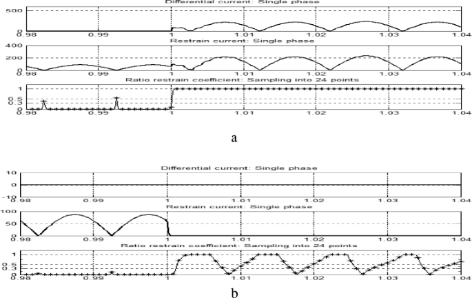
The differential current, restrain current and ratio restrain coefficient of the EBDP I. a The wide differential current of Bus I. b The differential current of Bus I
Figure 10 indicates that the WCDP of EBDP I adopts the currents at the D1, D3, D5, D10, D11 and D16 to calculate the differential current. If the ratio restrain coefficient is set to 0.3, the WCDP will start the EDBP I after 5 ms, and the specific CDP for Bus I, which adopts the currents at D2, D4, D6, D9, D11 and D15 will not operate correctly. It indicates that the fault occurs outside Bus I.
-
2)
Fault at F4 with PV 2# removed
If PV 2# is not connected to the micro-grid, the power flow direction on line L2 in Fig. 9 will change, i.e. from L2 to Bus III, and thus, L2 is included in the area of EBDP III. For the same three-phase short circuit fault at F4 on L2 at 1 s, the differential current, the restrain current and ratio restrain coefficient of the EBDP III are shown in Fig. 11.
Fig. 11 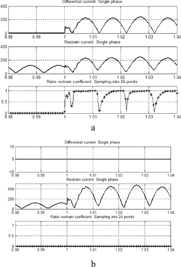
The differential current, restrain current and ratio restrain coefficient of the EBDP III. a The wide differential current of Bus III. b The differential current of Bus III
Figure 11 shows that the WCDP of EBDP III adopts the currents at the D15, D17, D18, D19, and D8 to calculate the differential current. For the ratio restrain coefficient of 0.3, the WCDP will start the EBDP III after 5 ms, and the specific CDP for Bus II, which adopts the currents at the D16, D17, D18, D19, and D7, will not operate correctly. It indicates that the fault occurs outside Bus II.
From Figs. 10 and 11 it can be seen that if the fault occurs in the protection area, the corresponding EBDP will operate correctly, otherwise, the EBDP will not operate correctly.
-
3)
Start time of the WCDP for each EBDP
For different types of faults, Table 2 shows the start times of the WCDP for each EBDP based on LWA with the coefficient of 0.3.
Table 2 Start times of the wide current differential protection It is shown in Table 2 that the start times of the wide current differential protection are all 5 ms with a ratio restrain coefficient of 0.3 for all types of fault.


5 Conclusion
This paper proposes an extended bus differential protection method based on the limited wide area for the relay protection in micro-grids with high penetration of DGs. In this method, the protection areas are divided at the core of the bus, and the WCDP is utilized to protect the whole protection area, whereas the CDP is used to protect each component in the protection area. Moreover, the protection areas can be changed according to the specific power flow direction. The effectiveness of the proposed technique is validated using simulations based on a real micro-grid system. The simulation results indicate that the proposed EBDP method can correctly trip the exact relays in any faulty conditions with less than 5 ms start-up time.
References
Fu-qiang, L., Shen, W.-d., et al. (2009). The analysis of the influence and measure of the power grid with grid-connected large-scale wind farms to the power grid of Jing jin tang. Electric Power Technology, 10, 44–48.
Zhao, P., & Yan, Y.-T. (2009). Research on effect of grid-connected photovoltai system on power grid. Electical Engineering, 3, 41–44.
Hua, L., Zheng-yang, L., et al. (2012). Research on the influence of wind-solar hybrid power supply system to the reliability of distribution network. Journal of Power Supply, 06(6), 92–96.
Girgis, A. A., & Brahma, S. M. (2001). Effect of distributed generation on protective device coordination in distribution system (pp. 115–119). Halifax, NS, Canada: Proc. Large Eng. Syst. Conf.
Brahma, S. M. (2004). Development of adaptive protection scheme for distribution systems with high penetration of distributed generation. IEEE Transactions on Power Delivery, 19(1), 56–63.
Novosel, D., Bartok, G., Hennerberg, G., et al. (2010). IEEE PSRC report on performance of relaying during wide-area stressed conditions. IEEE Transactions on Power Delivery, 25(1), 3–17.
Wide Area Protection and Emergency Control, Working group C-6, system protection subcommittee IEEE PES power system relaying committee final report, 2002
Adamiak, M. G., et al. (2006). Wide area protection: technology and infrastructures. IEEE Transactions on Power Delivery, 21(1), 601–609.
Miroslav, B., Damir, N., Daniel, K., et al. (2005). Wide-area protection and emergency control. Proceedings of the IEEE, 5, 876–891.
Wei, C., Pan, Z.-c., Jian-guo, Z., et al. (2006). A wide area protective relaying system based on current differential protection principle. Power System Technology, 30(5), 91–95.
Sheng, S., Xian-zhong, D., Xiang-jun, Z., et al. (2005). A multi-agent based wide-area current differential protection system. Power System Technology, 29(14), 15–19.
En-shu, J., Ma, Z.-t., & Ya-xiao, C. (2015). The hierarchical protection strategy research of intelligent substation based on the principle of current differential. Journal of Northeast Dianli University, 35(3), 12–17.
En-shu, J., Wang, Y.-c., & Chen, X. I.-f. (2014). Fault identification algorithm based on zon-division wide protection system. Power System Protection and Control, 42(9), 68–73.
Xiang-gen, Y., Zhen-xing, L., & Ying-tong, L. (2012). Study on wide area relaying protection and fault element identification. Power System Protecion and Control, 40(5), 1–9.
Run-bin, C., et al. (2014). Implementation of digital integrated protection and control system. Electric Power Automation Equipment, 34(5), 149–155.
Competing interests
The authors declare that they have no competing interests.
Author information
Authors and Affiliations
Corresponding author
Rights and permissions
Open Access This article is distributed under the terms of the Creative Commons Attribution 4.0 International License (http://creativecommons.org/licenses/by/4.0/), which permits unrestricted use, distribution, and reproduction in any medium, provided you give appropriate credit to the original author(s) and the source, provide a link to the Creative Commons license, and indicate if changes were made.
About this article

Cite this article
Wu, S. An adaptive limited wide area differential protection for power grid with micro-sources. Prot Control Mod Power Syst 2, 21 (2017). https://doi.org/10.1186/s41601-017-0052-2
Received:
Accepted:
Published:
DOI: https://doi.org/10.1186/s41601-017-0052-2